Attenuator and Dummyload
I wanted to expand the usability of my TinySA Spectrum Analyzer, by creating an attenuator, as completely basic ´can be described as an electrical resistance, to lower the strength/power of RF signals.
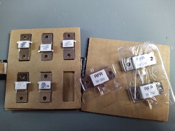
When I made the attenuators project I first was guided to make a circuit of resistors, twisted to match inductance and capacitance, to 50 Ω. Instead I went with the simple solution with a flange attenuators mounted on a heatsink. I got the idea to reuse the heatsink, by adding a flange resister to be used as dummyload for my radio.
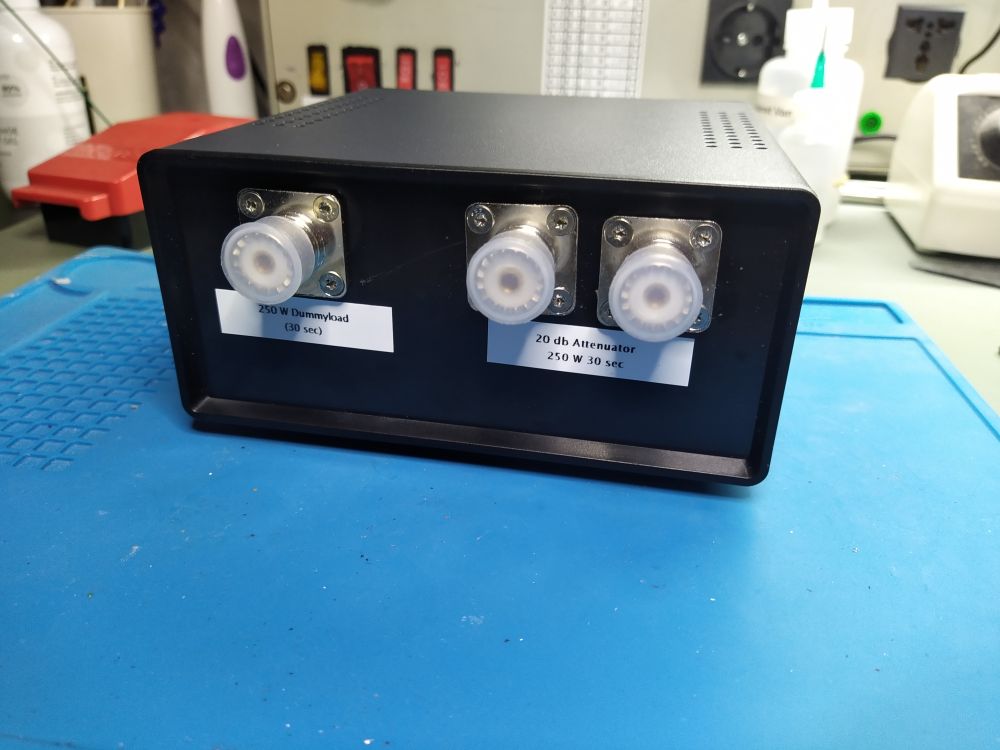
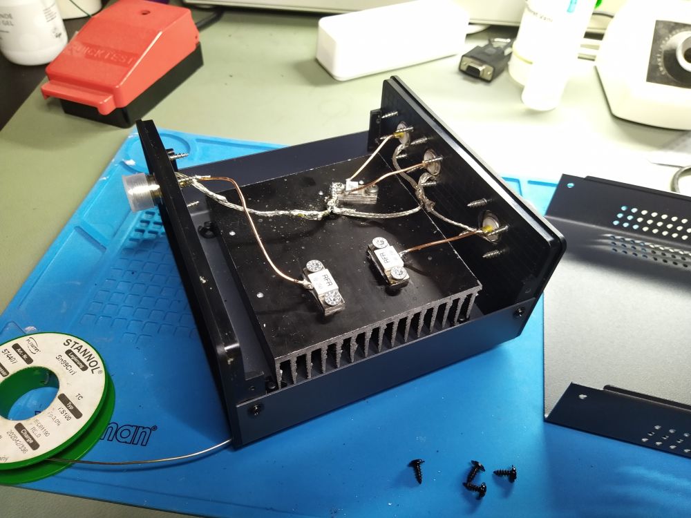
I connected both sides of the flange attenuator to PL-sockets on the frontpanel and shielding to the flanges and heatsink. I put a flange termination as dummyload next to the attenuator on the heatsink. There was room enough, so I added an additional flange terminations, connected to an PL-socket on the backpanel, to have a fixed dummyload connected to the radio. Then the attenuator and dummyload on the frontpanel meant to be used on the bench.
The size of the heatsink could be bigger, but I do not expect to run the attenuator and dummyloads on the same time.
I used the shield from a RG58 for the ground connection, to stiffen it, I added soldering tin to prevent a short, to the centre conductor.
I attend to add a 10 dB flange attenuator in series with the 20 dB flange attenuator and a PL-sockets so I can extend the use of the attenuator, to give 10 dB, 20 dB, or 30 dB damping of an RF signal.

BOM:
- 20 dB FLANGE Attenuator 150W
- 50 Ω 250W Resistor for a dummyload
- PL sockets
- Project case
- Heatsink

